Compressor stations consist of a compressor and different other components, which are necessary for their operation.
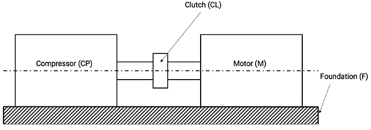
The motor M is usually an electric motor and is connected to the compressor CP via the clutch CL. The compression unit is represented by the compressor and the motor. It is installed on a common foundation F, see Figure 2.3. In a machine dynamic sense, that is in relation to variations in compressor speed, foundation stresses and vibrations, the compressor station has to be considered as a unit.
Figure 2.3: Structure of a compression unit [0]
From a thermodynamic point of view, all working chambers (WC) of all stages and the corresponding interstage system form a unit.
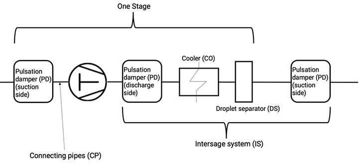
The Cooler (CO), the connecting pipes (CP), the pulsation dampeners (PD) on both sides of the working chambers (to reduce gas pulsations) and the droplet separators DS to remove condensed fractions and entrained lubricating oil belong to the interstage system, see Figure 2.4.
Figure 2.4: Schematic structure of an interstage system and one-stage system [0]
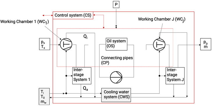
Usually, a compressor station is fitted with a cooling water system CWS for the working chambers and for interstage cooling, there is also an oil system OS for the lubrication of the crank drive and the cylinders, see Figure 2.5.
Figure 2.5: Schematic of a compressor station [0]
The control system CS regulates the startup and shut down procedures and controls the compressor according to changing working conditions. It also monitors the compressor station in order to avoid damage and to initiate repairs in dependence of the condition of its components.