The gas flow in and out of the cylinder is controlled by self-actuated, that is gas pressure controlled in- and outlet valves (suction and discharge valves). Table 4.7 shows the basic of dynamic valve calculation.
Designs and installation
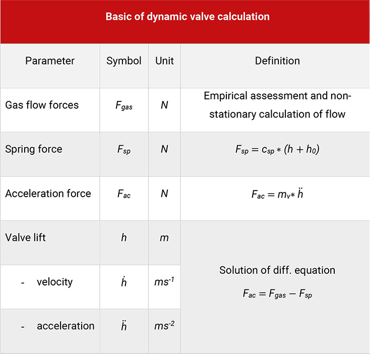
Table 4.7: Basic of dynamic valve calculation
In small and single acting compressors with a relatively high number of revolutions per minute preferentially reed valves are used. In medium and large piston compressors nearly always ring or plate valves find application, in special cases also poppet valves, [21].
With ring valves (Figure 4.16) the valve seat (1) is a plate with slots of concentric circular shape, which are connected by bridges. The free ring areas in the valve seat are sealed by individual non-metallic rings (3), which are held against the seat by coil springs (4,5), which in turn are enclosed on the circumference by spring pockets. After building up of a sufficiently high-pressure difference over the valve ring, the valve opens in a relatively short period. Another plate with concentric circular slots acts, the so-called valve guard (2) limits the valve lift. A central bolt (6) keeps the seat and guard in position.
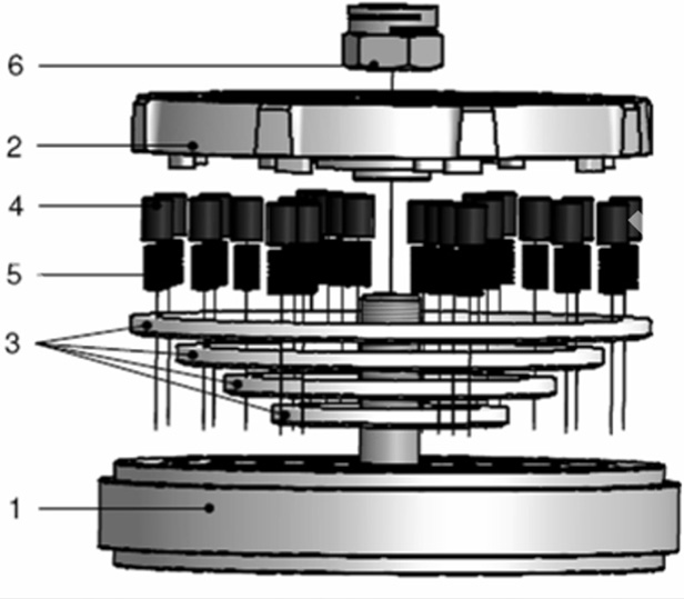
Figure 4.16: Schematic structure of a ring valve [0]
With plate valves, the seat ports are closed by a common valve plate made from steel or from non-metallic material, which again is fitted with slots. Suction and discharge valves are of the same basic design and only differ with the location of seat and guard in relation to the working chamber, see Figure 4.17.
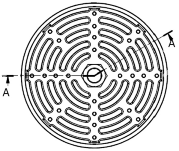
Figure 4.17: Plate valve – top view [0]
For proper functioning of the compressor valves the installation in the cylinder has to be adequately designed, see Table 4.8.
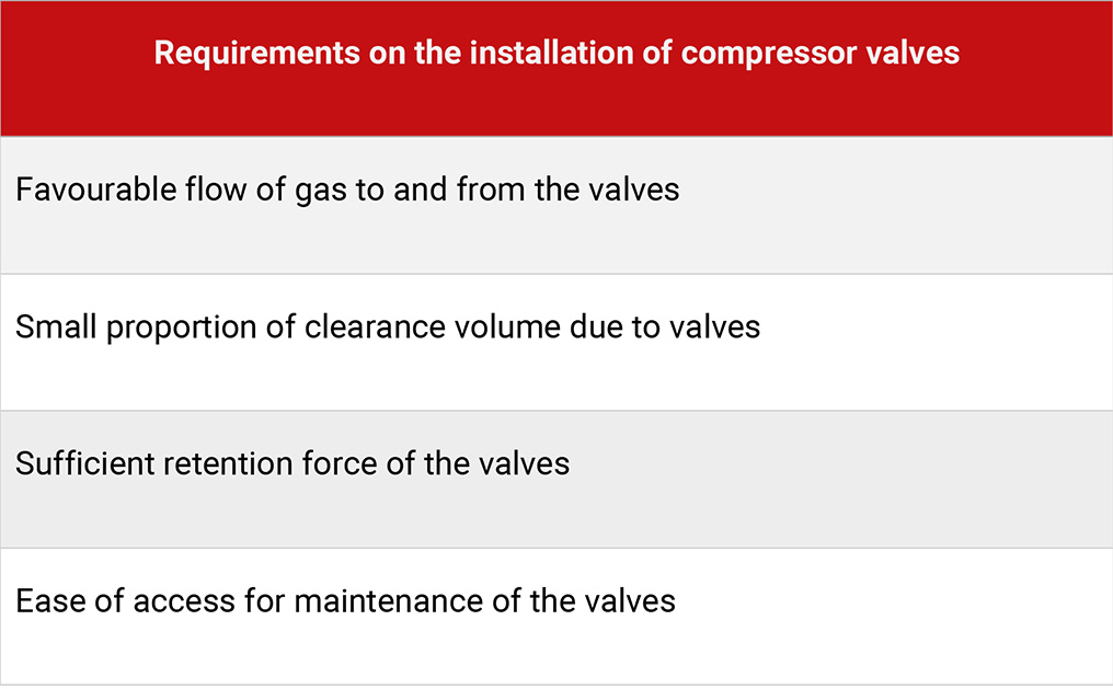
Table 4.8: Requirements on the installation of compressor valves
Installation 1 (Figure 4.18, left picture): Suction and discharge valve are located next to each other in the cylinder cover. The additional clearance volume remains thereby small. The available valve area is, however, very limited. The positioning of the valves is carried out via valve cages and bolts, which are fitted in the valve covers. These have to be sufficiently strong. This design enables easy access to the valves for servicing.
Installation 2 (Figure 4.18, middle picture): By arranging suction and discharge valve concentrically, the valve cover area can be fully used. In order to avoid excessive heat transfer from the warm gas on the discharge side to the gas on the suction side, both valve chambers are separated by a cooled compartment.
Installation 1 and 2 are typically used for simple plunger type compressors.
Installation 3 (Figure 4.18, right picture): With crosshead compressors, valves are preferentially fitted on the circumference of the cylinder. Thereby valves with larger passage areas for higher volume flows can be realised, which results in smaller pressure drops but also entails larger clearance volumes.

Figure 4.18: Different installations of compressor valves [0]
With reed valves, the closing of the seat area is done via a self-actuated or spring-loaded strip of spring steel, the reed. Thereby the design is simple and moving masses are low. This design is especially suited for fast running compressors.
When using reed valves, the cylinder head has to be adapted to the reed valve design and has to incorporate large valve chambers (6,7), see Figure 4.19. The common cylinder block (5) of a two-cylinder compressor is fitted with a sufficiently stiff common seat plate (1). The suction reeds (2) open into the working chamber and are limited in lift by a stop face on the cylinder circumference. The discharge reeds (3) have a guard (4).
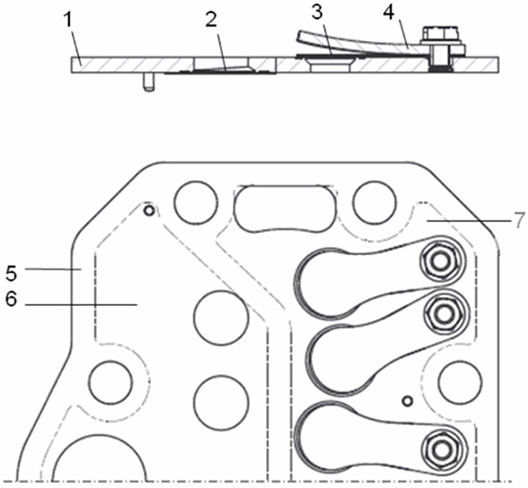
Figure 4.19: Schematic structure of a reed valve [0]
Layout
The passage area within the seat is called seat area. With fully opened valve, the passage area will be given free between seat and the closing device (i.e. ring, plate, reed). This passage area is proportional to the maximum valve lift.
For smaller pressure losses large seat areas and valve passage areas are of advantage. To have the passage area larger than the seat area (opening ratio > 1) does not result in lower pressure losses and increases the dynamic stresses of the moving valve components.
With the static valve calculation (see Table 4.9), the pressure losses are taken as the dynamic pressure loss at a characteristic gas velocity. This results as continuity calculation with the so-called equivalent area of the valve and the mean value of the piston velocity over valve opening time.
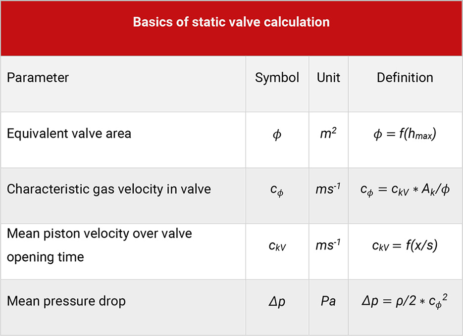
Table 4.9: Basics on static valve calculation
Experience shows, the ratio of equivalent area to nest area (valve efficiency VE) depends only on the maximum lift. Profiled ring valves have a better flow pattern and therefore a higher valve efficiency value.
In order to ensure a sufficient valve life, the behaviour of valve motion during opening and closing (valve dynamics) has to fulfil the following criteria:
The impact velocity of the valve plate on the guard should not exceed a limit of 3 to 4 ms-1 (depending on plate material and design).
While closing there should be no reversal of movement (valve flutter) and the valve should be closed with only small delay in relation to the piston reaching top dead centre (late closure), see Figure 4.20.
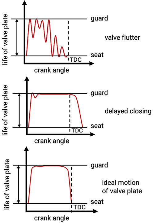
Figure 4.20: Ideal motion of valve plate in comparison to delayed closing and valve flutter [0]
With the dynamic valve calculation, the valve lift over valve opening time is calculated from the balance of forces acting on the valve plate. The enclosed graphs show the result of such a calculation for the opening motion of a suction valve in a hydrogen compressor. Figure 4.21 shows the valve lift of the suction valve while opening.
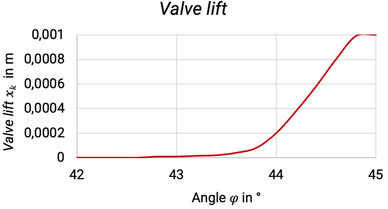
Figure 4.21: Valve lift of suction valve while opening [0]
As long as the suction effect of the movement of the piston is not balanced by the volume flow of gas entering the working chamber the cylinder pressure will decrease, see Figure 4.22.
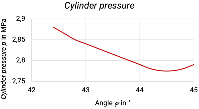
Figure 4.22: Cylinder pressure [0]
Figure 4.23 shows the mass flow of gas entering the working chamber.
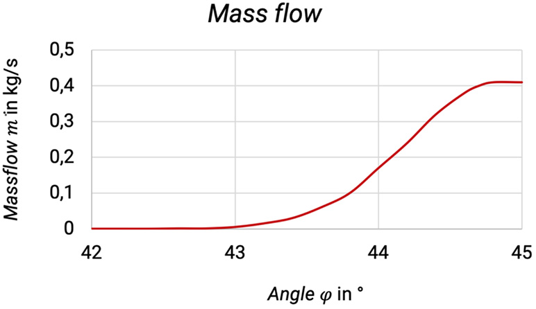
Figure 4.23: Mass flow of gas, which enters the working chamber [0]
Thereby the gas force and the acceleration force on the valve ring will increase, see Figure 4.24.
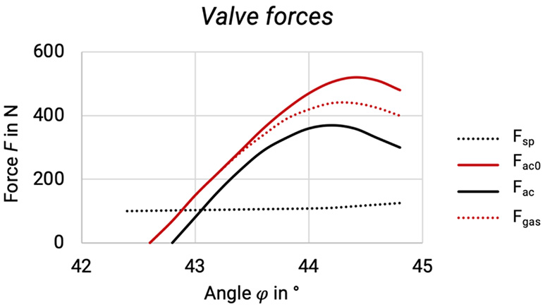
Figure 4.24: Valve forces on valve ring [0]
Due to the increasing acceleration the valve plate, the velocity will increase progressively. On impact on the guard (h = hmax = 1 mm) this velocity will be approx. 3,4 ms-1.
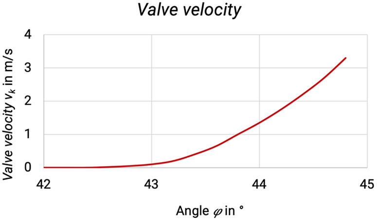
Figure 4.25: Valve velocity [0]
Figure 4.26 shows the valve acceleration during the suction process.
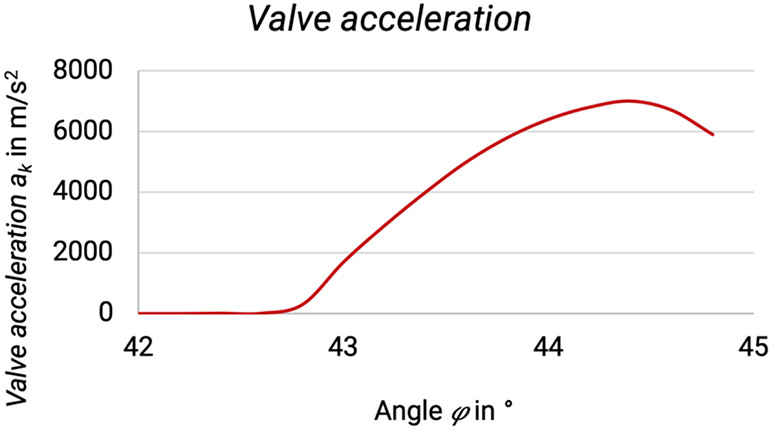
Figure 4.26: Valve acceleration during suction process [0]
More recent investigations ([15], [16], [23], [35], [37], [38]) have shown, that the gas dynamic force can only be calculated realistically, if the occurring gas pulsations are taken into account.
