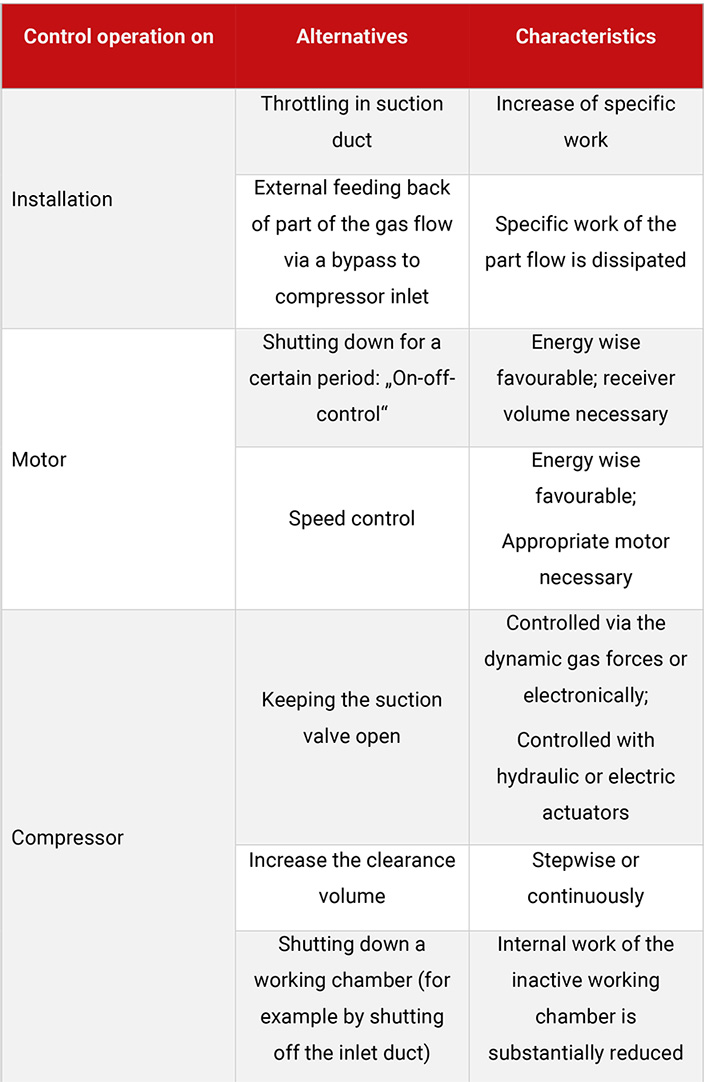
This is a preferred method on multistage compressors fitted with ring or plate valves if speed control is not possible due to the design of the motor drive or if the speed control range is not sufficient for the necessary reduction in volume flow.
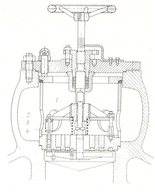
The control of the suction valve in its simplest form is carried out via a spring-loaded unloader. The force on the suction valve unloader, which acts against the closing force of the valve plate, can be adjusted via the pretension of the spring. The valve closes only at that point where the drag force acting in the direction of valve closure exceeds the spring force. The intake of gas is thereby reduced.
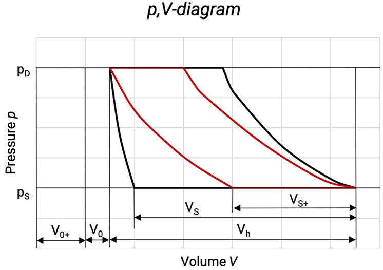
With this kind of regulation, the specific compression work for the gas will be increased. This results from the pressure difference between gas intake and gas discharge when the suction valve is held open.
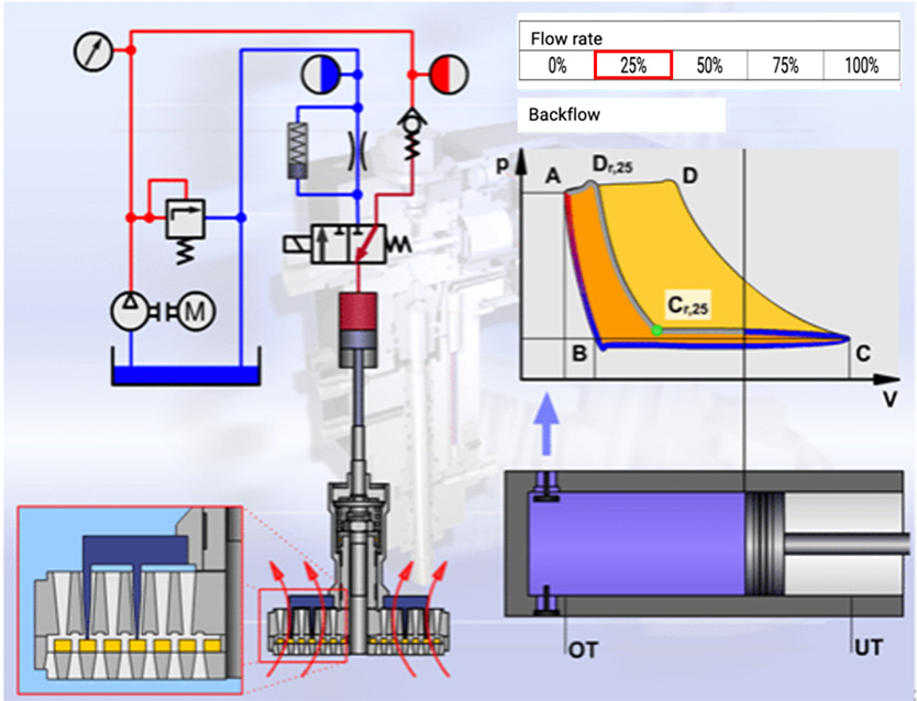
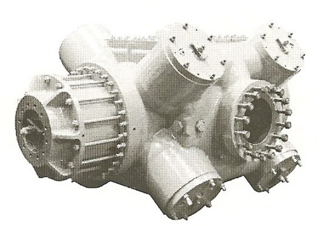
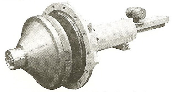
In compressor installations, controlling the suction valve via hydraulically operated and electronically controlled actuators [37] has been widely accepted, see Figure 6.3. The suction valve unloader is actuated by a hydraulic cylinder, which in turn is controlled via a solenoid valve. The control signal is generated in an electronic unit that receives its information about the actual position of the piston from a top dead centre sensor and of the mass flow requirement from the process control system of the plant.
Figure 6.3: Control of suction valve in compressor installations via hydraulically operated controlled actuators [0]
The advantages of this combined control system lie in the fast response and the freely programmable reaction of the movement of the suction valve unloader. This system can coordinate the control of all regulated suction valves, so that also at part load the interstage pressures can be kept at the desired levels. This control can also be used for unloaded start up to reduce the load on the motor.
Figure 6.4: Cross section of a suction valve unloader [0]
