Cylinders comprise the working chambers, the compressor valves and the cylinder cooling. The design of the cylinder is adapted to the specific pumping duty.
Function and types

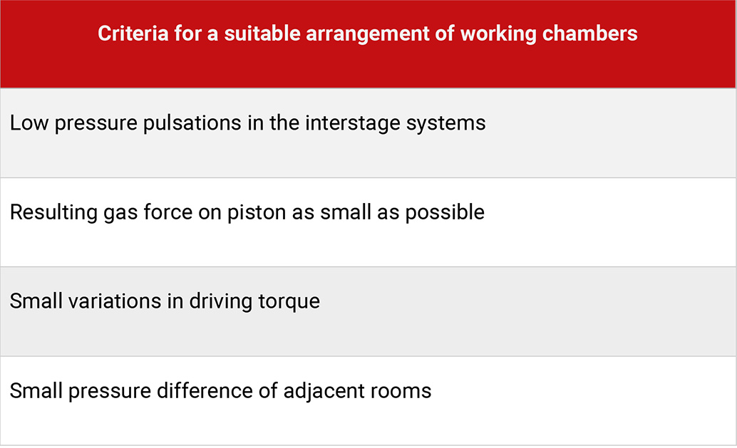
Table 4.4: Criteria for suitable arrangement of working chambers
The number and size of the working chambers is defined by the thermodynamic function of the compressor. Several working chambers can be fitted within one cylinder.
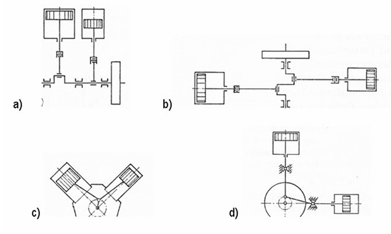
The arrangement of the cylinder axes influences the design of the crank shaft and the mechanical stresses of the compressor. In a compressor with in-line cylinders, the axes of the cylinders are parallel and are at right angles to the crankshaft.
In general, the axes are in a vertical plane, therefore also called a vertical piston arrangement (see Figure 4.7, a). If the cylinders are arranged in two opposite groups, the compressor is of the boxer type (balanced-opposed piston). The axis of the cylinders is then mostly in a horizontal plane (see Figure 4.7, b). If the cylinders are arranged in two planes which are at an angle to each other it is called a V design. A V-angle of 90 degrees is favourable for the balance of the mass forces (Figure 4.7, c). A special case is the arrangement of both vertical and horizontal cylinder axis (vertical / horizontal design), see Figure 4.7, d).

Figure 4.7: Different arrangements of cylinders [0]
Examples of design
The design of the cylinder depends largely on the valve arrangement. In addition, the cooling, lubrication and the cylinder pressure are influencing factors.

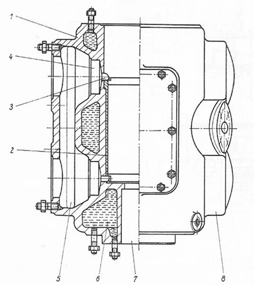
Figure 4.8: Example 1 – Low-pressure compressor [0]
The water-cooled cylinder (1) has double walls. The inner cylinder wall carries the liner (2). On its top it is fitted with the cylinder head, the lower part is equipped with a pressure packing (7), which seals the piston rod passage.
Valve nests (4) at the circumference of the inner cylinder wall accommodated the valves. The slots (3) connect the valve chambers to the working chamber. The outer cylinder walls have openings, through which the valves can be mounted. The suction and discharge valves of both working chambers each have common chambers (5,8).

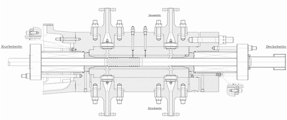
Figure 4.9: Example 2 – Highest-pressure compressor [0]
For Highest-pressure compressor, the cylinders are manufactured in several layers from impact resistant alloy steel. The innermost layer works as a wear resistant liner. The middle and the outer section are shrunk together. This shrinking results in compression stresses, which counteract the tensional stresses caused by the high working chamber pressure [34].
The cylinder lubrication on crosshead machines is carried out by lubricators, where the lubrication rate can be adjusted (via adjustable pistons), on plunger type piston compressors via splash lubrication. The amount of lubrication is thereby difficult to control.

