The driving gear of the compressor converts the rotating motion of the crank into the oscillating motion of the piston and transmits work. It usually works according to the kinematic principle of the connecting rod mechanism.
Function and variations
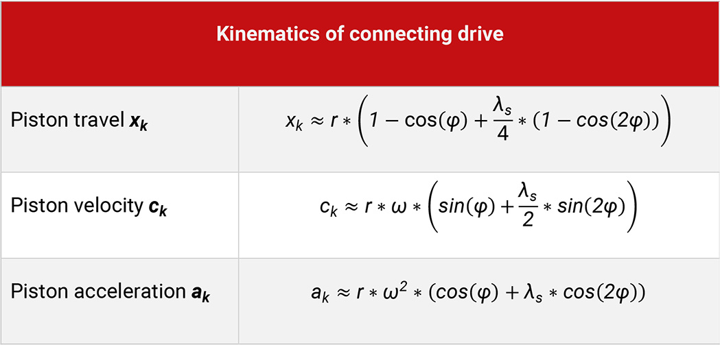
Table 4.1: Calculation of kinematics of connecting drive
For single-acting compressors usually, the connecting rod is directly linked to the piston (plunger type piston – Figure 4.1, a), whereas for double-acting compressors linear reciprocating motion is achieved by linking the connecting rod to the crosshead (crosshead design – Figure 4.1, b). On very small compressors (for example with household refrigerators), the kinematic principle of the scotch yoke (Figure 4.1, c) will find application. It is a four-member link with two linear guides.
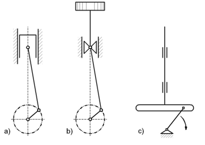
Figure 4.1: Kinematic principles of different compressors [0]
Small fast running units can be designed as axial compressors. Thereby several pistons are running in parallel to the axis of the drive of the machine. The pistons are moved via a disc fitted at an angle to the drive shaft (swash plate), see Figure 4.2, f).
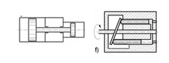
Figure 4.2: free piston (left) and axial piston compressor (right) [0]
For (combustion) engine driven compressors the free piston assembly is an interesting alternative. The reciprocating action of the combustion engine is directly linked to the oscillating motion of the compressor. As the free piston combustion is based on the counteracting combustion processes in the two combustion chambers, proper timing of the double-acting motion is crucial.
Kinematics and dynamics
The connecting rod drive results in an oscillating and nearly harmonic movement of the piston. The piston velocity and acceleration can be calculated with sufficient accuracy by a Fourier series of 2nd order. The deviations from the harmonic motion increase with the rod ratio λ, which is the relation of crank radius to connecting rod length.
Primarily the drive will be loaded by the force F resulting from the gas pressure acting on the piston (gas force). The resulting loads onto the individual components can be calculated according to the laws of statics.
The vertical force FN acts on the guides of the crosshead acts, whilst the force FS acts on the connecting rod. At the crank bearing the connecting rod force FS can be split up into two orthogonal forces. The tangential force FT together with the radius of the crank results in the torque, see Figure 4.3.

Figure 4.3: Occurring forces due to the F resulting from the gas pressure [33]
The gas forces within the machine are balanced. Only the tipping moment (as a result of the torque of the drive) shows an effect on the surroundings.
Mass forces result as a reaction to the continuously necessary accelerations of the oscillating parts of the drive mechanism. These can be calculated according to Newton’s law of motion as the product of moving mass times their acceleration. The piston travel, the piston velocity and piston acceleration for two different rod ratios depending on the crank angle phi are shown in Figure 4.4, Figure 4.5 and Figure 4.6, respectively.
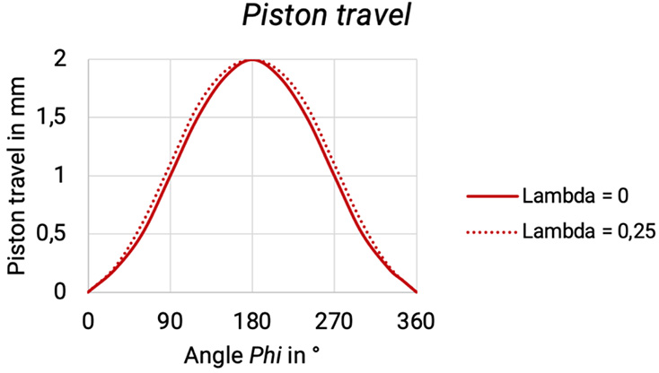
Figure 4.4: Piston travel depending on phi [0]
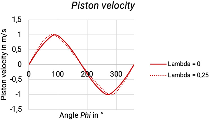
Figure 4.5: Piston velocity depending on phi [0]
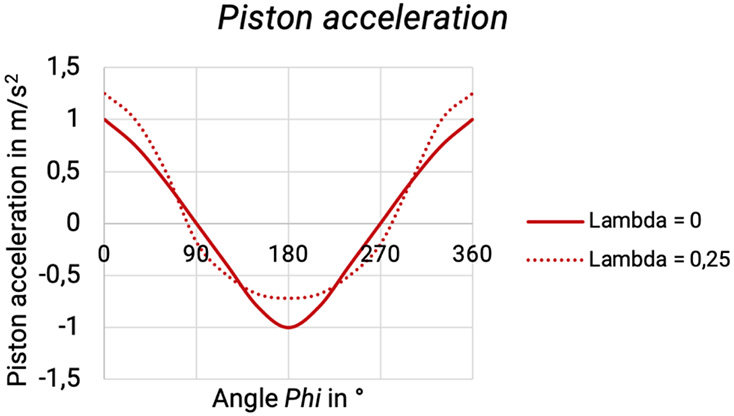
Figure 4.6: Piston acceleration depending on phi [0]
Contrary to the gas forces, the mass forces act in full also to the outside and onto the foundations (also via their torques). Therefore, on multi-cylinder machines an optimal balance of the mass forces by an appropriate design of crank and cylinder arrangement is an important design goal.
Design series
In order to be able to manufacture at low cost, compressor manufacturers mostly use well-proven, standardised drive designs in various sizes. To achieve smaller dimensions, the compressor speed should be as high as possible.
However, considering lifetime and efficiency, the mean piston speed should not exceed certain limits. The smallest values apply to non-lubricated service and for highest pressures, the biggest for small plunger type compressors with intermittent service. The compressor speed is also limited by the maximum allowable working frequency fV,all of the self-actuated compressor valves. The maximum allowable piston forces of a certain compressor drive series rise approximately with the square of the stroke, see Table 4.2.
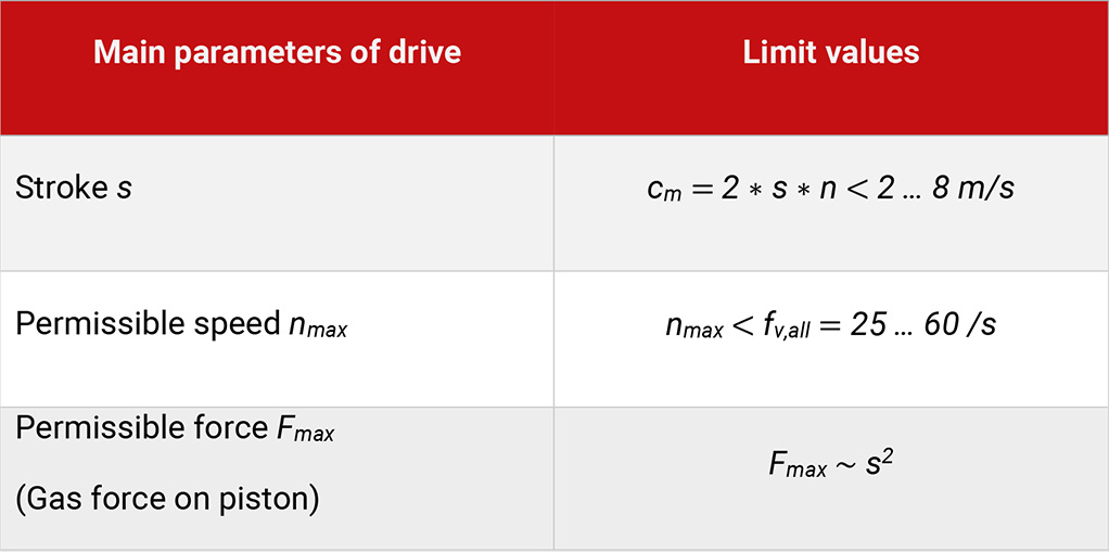
Table 4.2: Main parameters and limiting values for compressor design
Table 4.3 shows the differences in oscillating and rotating movement of compressors.
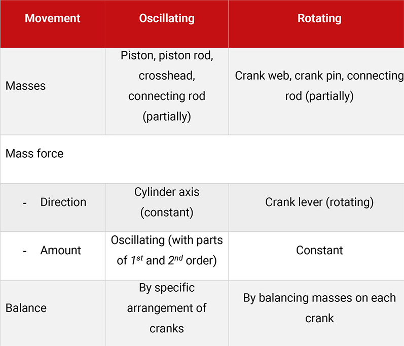
Table 4.3: Comparison between oscillating and rotating movement

