The quasi stationary changes in the conditions of state of the gas when flowing through a compressor stage can be represented in a T,s-diagram, see Figure 5.5.
Changes in the conditions of state of the gas
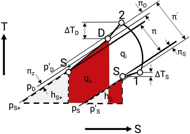
Figure 5.5: T,s-diagram of the quasi-stationary changes in the condition of state of a gas through a compressor stage [0]
Such a compressor stage can be either part of a multistage or a single-stage compressor.
Gas enters the cylinder from the suction chamber in the condition S. During the flow into the cylinder throttling and heating up of the gas occur.
The non-stationary change of state in the working chamber is limited by points 1 and 2 of condition of state at the beginning and at the end of compression. For the quasi-stationary evaluation of the stage, the mean pressures during the intake and discharge are relevant.
The outflow of gas out of the working chamber is combined with a pressure loss and a cooling of the gas down to the conditions of the receiver D on the discharge side.
With the gas, flowing through the interstage system its temperature will be reduced to the suction temperature TS+ of the next stage. The pressure is reduced due to friction losses to pS+. (The index + symbolizes the next stage).
For the function of the stage the pressure ratios below are characteristic. (All pressure ratios correlate to a line in the T,s-diagram.), see Table 5.2.
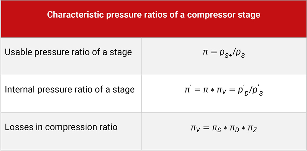
Table 5.2: Characteristic pressure ratios for a compressor stage
According to the first law of thermodynamics the specific work put into a stage equals the heat removed from the working chamber and the interstage system plus the mostly relatively small change in enthalpy of that stage, see Table 5.3.
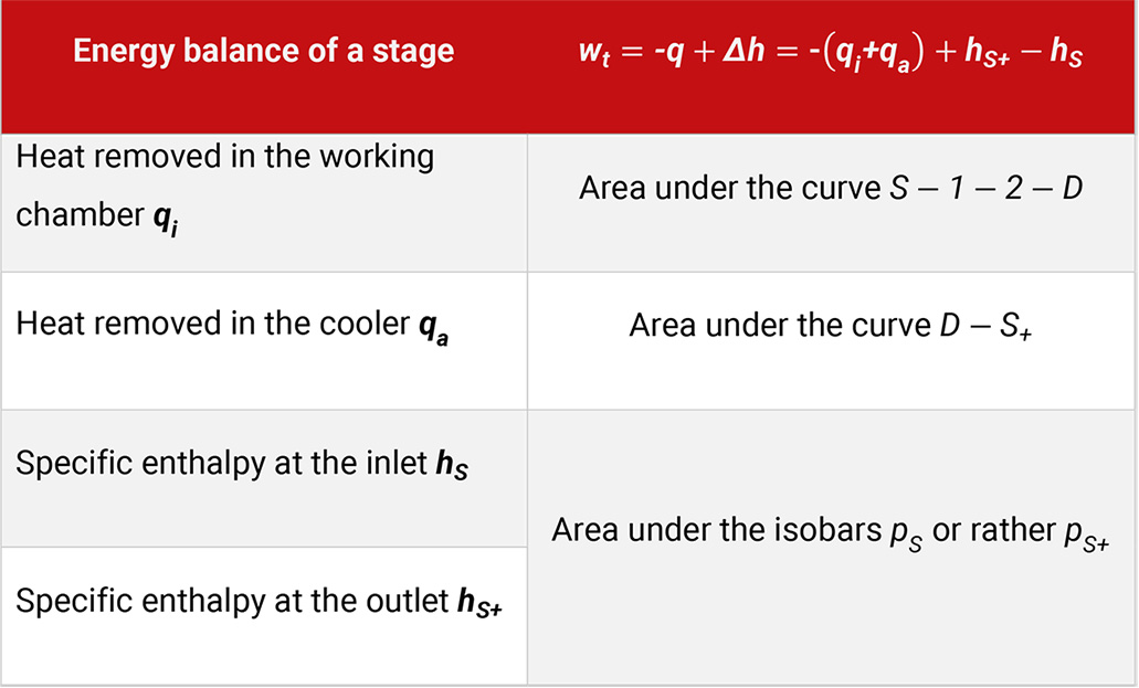
Table 5.3: Specific energy balance of a compressor stage
Transport of liquid and liquid separation
Usually the gas contains a certain amount of water vapour, in the extreme case it can be saturated with water vapour. For the absolute humidity (mass ratio of water vapour to dry gas) there exists a limit, which is proportional to the ratio of vapour generation pressure and the pressure of the gas, see Table 5.4.
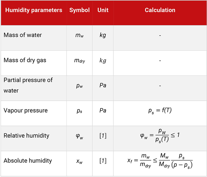
Table 5.4: Humidity parameters and calculation
The temperature and thereby the vapour pressure at the inlet of subsequent stages only differ slightly. Therefore, with rising pressure of the gas from stage to stage its capacity for the solubility of water as vapour is reduced and partly condensation occurs. The condensate in the form of droplets has to be removed, as accumulation of water could lead to damage in the next compressor stage (water hammer, corrosion).
The oil content of the gas behind a lubricated compressor stage typically lies in the order of 10 mgoil / kggas. The diameter of the droplets is 0.1 to 10 µm (most frequent occurrence at approx. 1 µm). These droplets result from being carried away from the oil film on the walls of the intercooler system by the gas flow. In addition, the oil should be separated behind each stage (designs and application of separators).
Non stationary flow and Gaspulsations
The flow of gas though the interstage systems is only stationary under ideal conditions. In the real compressor, the flow cannot be stationary. The periodic compression cycle in the working chambers, result in changing flow velocities and causes therefore periodic quasi-stationary pressure changes in the interstage system. These pressure changes are the smaller, the smaller the flow difference of inlet and outlet and the larger the volume of the interstage system.
Each component of a compressor unit where gas flows through constitutes an oscillating mass-spring system, as the component contains a gas mass with an inner elasticity (compressibility), see Table 5.5.
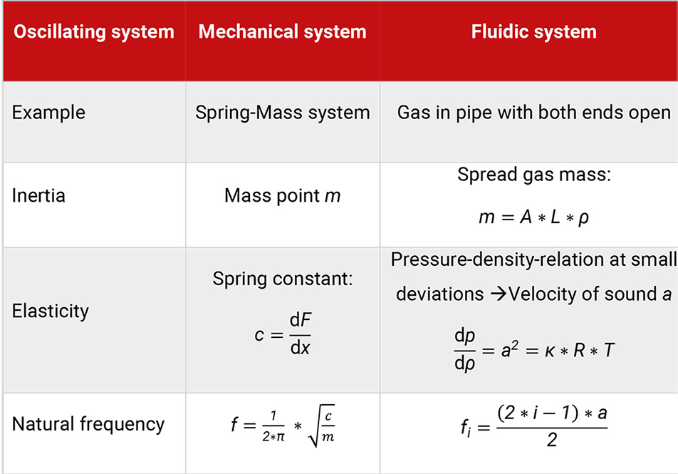
Table 5.5: Comparison between mechanical and fluidic systems
The simplest shape of such a system is a straight tube. In a tube, the gas can carry out longitudinal oscillations. Thereby the basic constant velocity of the gas is superimposed by periodic velocity oscillations propagating in the direction of the flow. Due to the principle of conservation of energy, the oscillations of velocity are linked to oscillations of pressure. The total of these non-steady state processes is called gas pulsations. The variations of pressure are normally small compared to the level of working pressure of the gas. They propagate with the speed of sound. They are therefore called acoustic oscillations.
Gas pulsations in compressor units result from the periodic feeding and removing of gas into or out of adjacent working chambers of the compressor cylinder. The pulsations are dampened through friction of the gas flow in the pipes and in all those chambers that influence the flow of gas.
The excitation of gas pulsations in a compressor plant occurs within a frequency spectrum consisting of the rotary frequency or its multiples (harmonics). A Fourier analysis of the gas inlet and outlet process can deliver the level of excitation of the individual harmonics. Through the installation of sufficiently large pulsation dampeners before and after the working cylinders, the generation of gas pulsations can be substantially reduced in all working conditions.
The local and temporary distribution of pressure fluctuations can be seen as the total sum of fluctuations at all excitation frequencies. This fact is normally taken into account when carrying out a calculation and an analysis of gas pulsations. (Alternatively, to the calculation with the frequency spectrum a more elaborate but more precise method of calculating the pressure pulsations can be carried out in the time domain.)
The gas pulsations also influence the thermodynamic function of the compressor installation, especially on the working valves. The transient forces are created by the gas on various components of the compressor installation. These forces are correlated to the gas pulsations and generate mechanical vibrations. The thereby created mechanical stresses depend strongly on the support and fastening of the individual components.
A pulsation analysis has to be carried out for all compressor installations already in the design stage. Its objective is to plan the layout in such a way, that the pressure pulsations will not endanger the thermodynamic function nor the mechanical strength at any point. The larger the compressor installation and the higher the operating pressure, the higher the demands on this pulsation analysis are (API 618 [6] and Table 5.6 right).
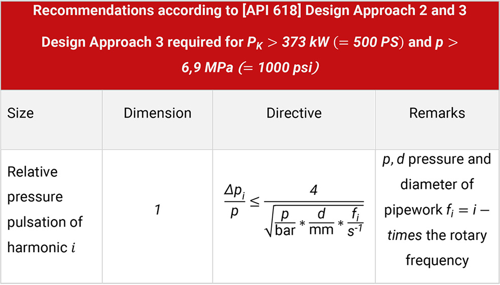
Table 5.6: Pulsation analysis
For medium and large size compressor installations the calculation of pressure pulsations and the overall pressure losses has to be carried out with well proven simulation programs for the actual working conditions and for all sub systems. These programs are composed of modules and allow a detailed simulation of the installation. For large installations, an analysis of the mechanical vibrations of all components has to be carried out. In addition, the influence of the gas pulsations on the operation of the compressor – and especially on the operation of the compressor valves – has to be checked.
The pulsation analysis has to be carried out for all operational points and for all compositions of the gas. Subsequently, an analysis of the mechanical reaction of the various installation components has to be carried out for the operating condition with the largest pressure pulsations. If allowable limits are exceeded, changes on the layout have to take place.
The fitting of throttles at appropriate places in the installation shifts the natural frequencies but increases the pressure loss and thereby the costs of the installation. The use of supports with better friction dampening is more expensive but avoids additional costs [22]. For the specific mitigation of defined pulsation frequencies, pulsation dampeners of the resonator principle may find application, see Table 5.7.
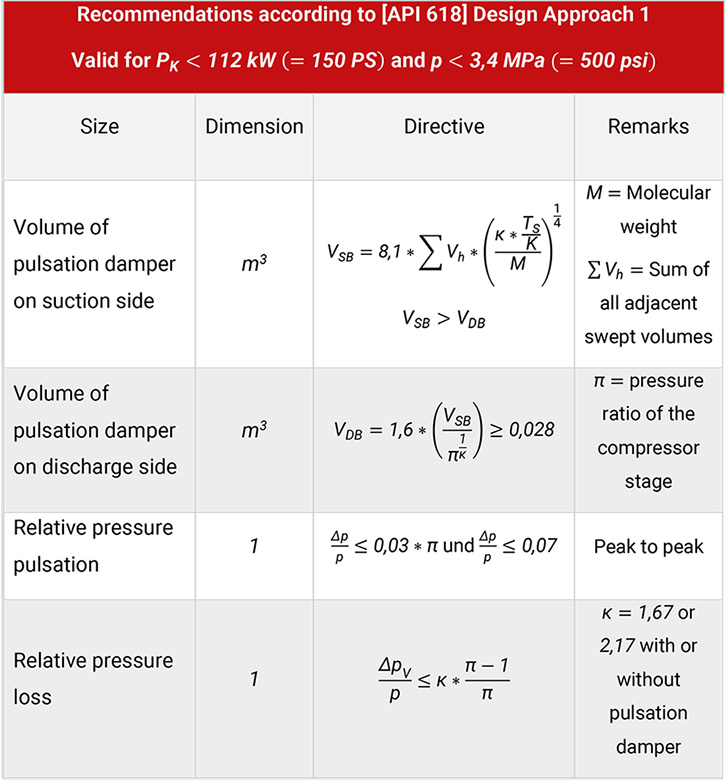
Table 5.7: Application of pulsation damper and its effect on different parameters

