This section is meant for those readers, who have no basic knowledge of thermodynamics so far, but who would like to be able to follow the thermodynamic considerations in the following chapters. For further information on thermodynamics we recommend for example [2].
Thermodynamic condition of state
The thermodynamic condition of state of a gas is described by three parameters, which are linked by a function, so that only two parameters (e.g. pressure and temperature) are necessary to define a condition of state.
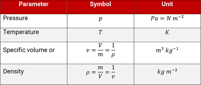
Table 1.1: Parameters to describe the condition of state of a gas
Over a large range of conditions this functional link is given with a good approximation by the simple characteristic equation of an ideal gas (see equation 1.1):
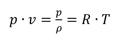
Equation 1.1
The characteristic gas constant R is defined by the type of gas. The product of R and the relative molecular mass is constant for all gases. The thermodynamic behavior of a gas is described by its isentropic exponent . The value of mainly depends on the number of atoms in the molecule of the gas.
Table 1.2 shows the characteristic gas constant and the isentropic exponent of different gases.
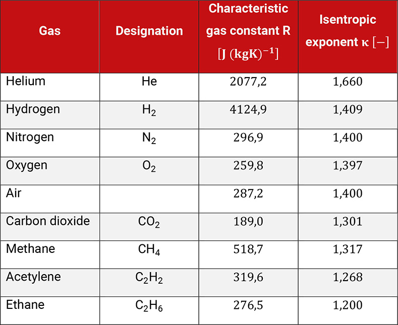
Table 1.2: Characteristic gas constant and isentropic exponent of different gases
The deviation of an ideal gas in comparison to a real gas becomes higher, the closer the gas condition is to the liquid state. This is called real gas behavior. In order to understand the working principles of compressors the assumption of ideal gas behavior is sufficient and the base for further considerations in the following chapters.
Variations of the conditions of state
The thermodynamic condition of state of one gas changes through external influences (on compressors by performing physical work or exchange of heat).
Changes of state without any internal losses are called internally reversible and are described by the polytropic equation. The polytropic exponent n characterizes this change of state.
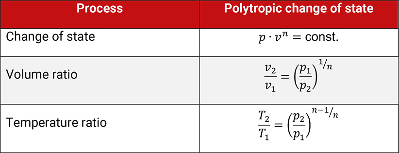
Table 1.3: Polytropic change of state
In order to evaluate such changes, parameters for changes of state for energy and processes are used. For the evaluation of the compression of gases the parameters technical work and heat q, also the thermal parameters enthalpy h and entropy s are preferentially used, showed in Table 1.4.
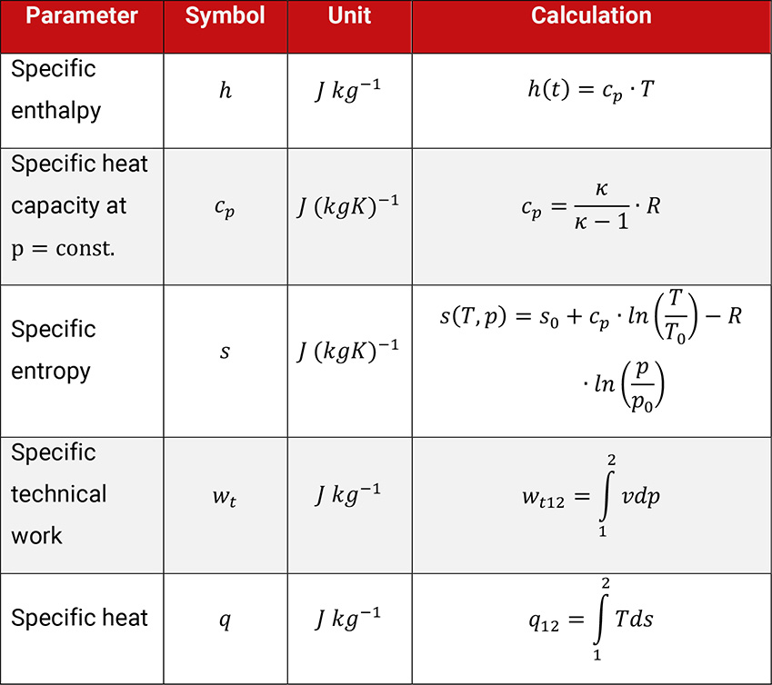
Table 1.4: Parameters to evaluate the change of thermodynamic condition of state of an ideal gas
For each change of state, the law of conservation of energy (first law of thermodynamics, see equation 1.2) applies. This law describes, that the input of technical work plus heat equals the increase in enthalpy of the gas for closed thermodynamic systems.

Equation 1.2
When compressing gas and applying cooling, the rise in temperature of the gas is proportional to the difference between the input of work and heat removed.
In order to evaluate energywise changes of state the following condition of state diagrams are used:
The p,v–diagram shows the reduction of the specific volume during the compression process from condition 1 to condition 2 (compare Figure 1.1). The larger the reduction, the smaller the polytropic exponent n. The technical work is given as the area between the compression curve and the ordinate. For the technical work is showed for example. The general definition of the technical work is shown in (equation 1.3):
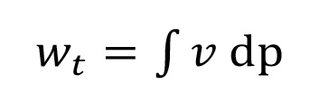
Equation 1.3
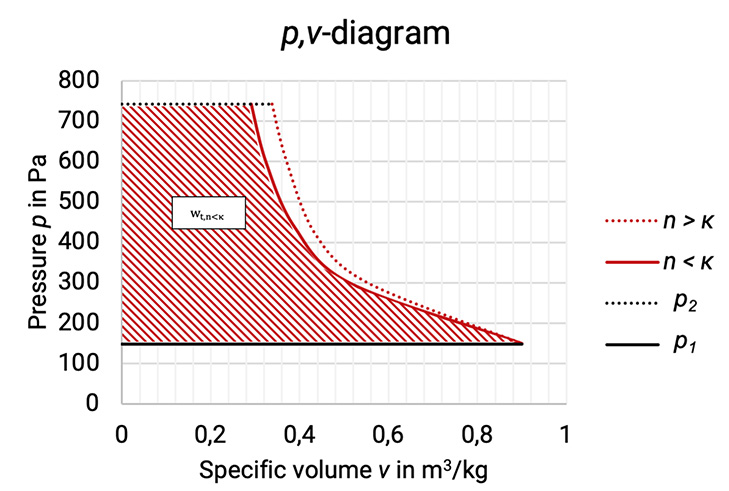
Figure 1.1: p,v–diagram of the compression process with different polytropic exponents [33]
The T,s–diagram shows the temperature rise when compressing a gas (see Figure 1.1 and Figure 1.2). If the gas is being cooled during compression, then and the entropy reduces (1 à 2.1, red curve). When heat is added (for example through friction of flow in turbo compressor rotor), then and the entropy increases (1 à 2.2, black curve). The amount of heat transferred or removed is given by the area under the curve.
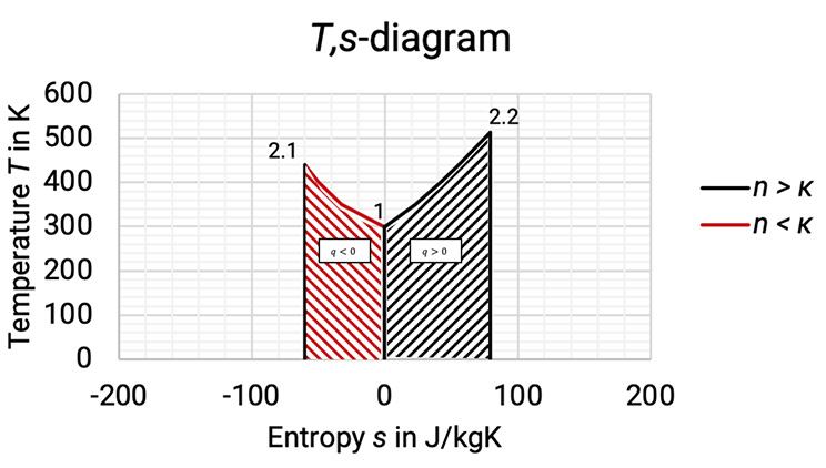
Figure 1.2: Comparison between compression with cooling and compression with added heat in T,s-diagram [0], [3]
Isothermal and Isentropic compression
Isothermal compression and isentropic compression are special cases of the polytropic process. They are of particular importance for gas compression:
Isothermal compression represents a non-achievable limit of a compression with ideal cooling (the cooling of the compressor requires a sufficiently high temperature difference to the coolant), see Figure 1.3.
Isentropic compression represents a non-cooled compression without internal losses, that cannot be realized in reality, see Figure 1.3.
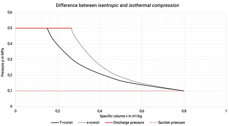
Figure 1.3: Difference between isentropic and isothermal compression in p,v-diagram [2], [33]
Table 1.5 gives the most important parameters for the evaluation of these two changes of state. Following the 1. law of thermodynamics, the same amount of heat has to be removed as technical work was done with the isothermal compression. With isentropic compression the increase of enthalpy is equal to the technical work done.
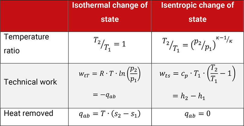
Table 1.5: Parameters for the evaluation of an isothermal and an isentropic change of state
The work done within the isothermal compression represents the theoretical minimum of required work and is therefore taken as a base value to compare with actual work done.
Multistage compression
The technical work done rises with the pressure while isentropic (non-cooled and reversible) and isothermal (ideally cooled) compression. The higher the isentropic exponent, the higher the increase of both, showed in Figure 1.4.
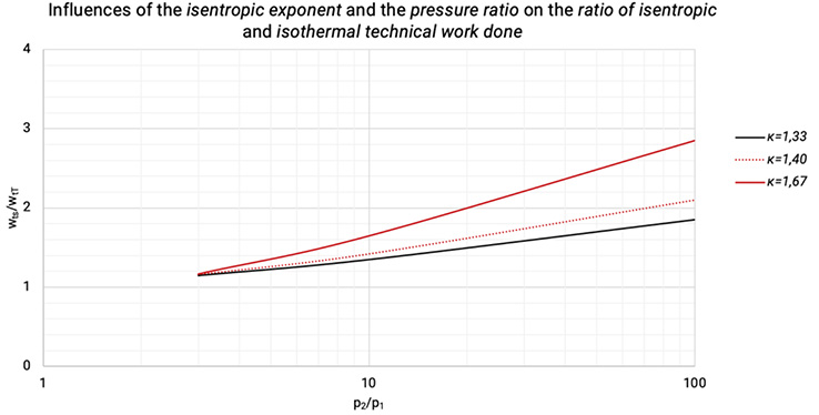
Figure 1.4: The influences of the isentropic exponent and the pressure ratio on the ratio of isentropic and isothermal technical work done [0], [3]
For safety reasons the outlet temperature is limited to a maximum of 135 to 200 degree Celsius, depending on the type of compressor and the application. This temperature range limits the allowable compression ratio in single-stage compression. However, multistage compression with cooling between the stages is also used to save energy. As an example, we examine an ideal two-stage compression (isentropic compression with total isobaric cooling back to suction temperature).
The p, v–diagram shows the approximation to an isothermal change of state and the reduction in specific work done, cf. Figure 1.6.
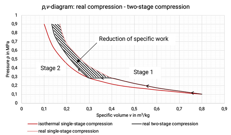
Figure 1.5: Comparison between real single-stage compression, isothermal single-stage compression and real two-stage compression and the reduction of specific work [0], [33]
The T,s–diagram shows the achieved reduction in discharge temperature, see Figure 1.6.
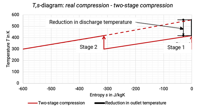
The Figure 1.6: Comparison between single-stage compression and two-stage compression process in T,s -diagram [0], [3]

