Process compressors used in the process industry (for example in the liquefaction, rectification and with chemical reaction of technical gases) have to fulfill demanding requirements in relation to performance and reliability.
Natural gas is a very important resource in the process industry. Its transport in gas pipelines or by tankers in the form of liquid natural gas, also its underground storage requires special natural gas compressors [0].
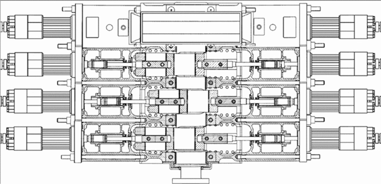
Preferably executions of process compressors in vertical and horizontal boxer design are being used, which fulfil the requirements of a specific standard for the oil and gas industry API 618, [6].
The throughput amounts up to 100000 m3h-1(related to standard condition), the discharge pressures up to 100 MPa (for specific applications up to 360 MPa).
The driving mechanisms are carried out in various sizes and with different number of cranks. They are designed for minimum deflection and the distance between the cylinders is kept to a minimum. The mean piston velocity goes up to 6 ms-1. The boxer design can achieve a full balance of mass forces and torque, if the design includes at least two pairs of cranks.
The cylinders are typically double acting and water-cooled. In the low-pressure stages, big compressor valves with sufficiently large valve chambers are necessary. This can more easily be done in boxer compressors. A pressure packing seals the working chamber at the crank side. The cylinder is connected to the crankcase via a distance piece, which transmits forces and centres the cylinder.
Figure 3.5: Boxer compressor, top view
Installations of compressors with vertical in-line cylinders need less space but have to be fitted with a platform for servicing the cylinders. With balanced opposed piston compressors, the coolers are arranged horizontally and parallel to the compressor on the foundation platform. With vertical cylinders, the coolers are arranged externally. In both cases, the pulsation dampeners are fitted vertically close to the cylinders.
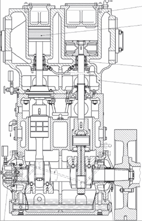
A special design for non-lubricated service is the labyrinth compressor, see Figure 3.6. On the vertically in-line arranged cylinders, the piston rods have an additional guidance on the lower end of the distance piece. This provides such an excellent guidance, that the pistons can run without touching the liner and with low clearance. Labyrinths on the circumference of the piston and in the packing allow oil-free compression with minimum leakage after a short running-in period. In order to prevent leakage of the compressed gas to the outside, the crankcase can be sealed gastight via a double acting sliding ring seal. This design is used for pressures up to 35 MPa.
Figure 3.6: Labyrinth piston compressor
For the manufacture of low-density polyethylene (ldPE) the ethylene has to be compressed to very high pressures. The secondary compressor as shown (Figure 3.7) is of the boxer design with pairs of cranks and compresses in two stages from 27 to 320 MPa.
Figure 3.7: Hyper compressor of the Company Burckhardt Compression
The drive mechanism is equipped with a frame type crosshead, which encloses the forked piston rod, and which drives the two coaxially arranged pistons via additional round crossheads in the distance pieces. The maximum rod load is 1,86 MN (186 t). A horizontal guidance is used to take up the vertical force. This guidance is arranged close to the foundation and is strongly dimensioned.
The cylinders are designed from geometrically simple parts with notch free shapes and polished surfaces. The parts are shrunk together, thereby providing preloading.


