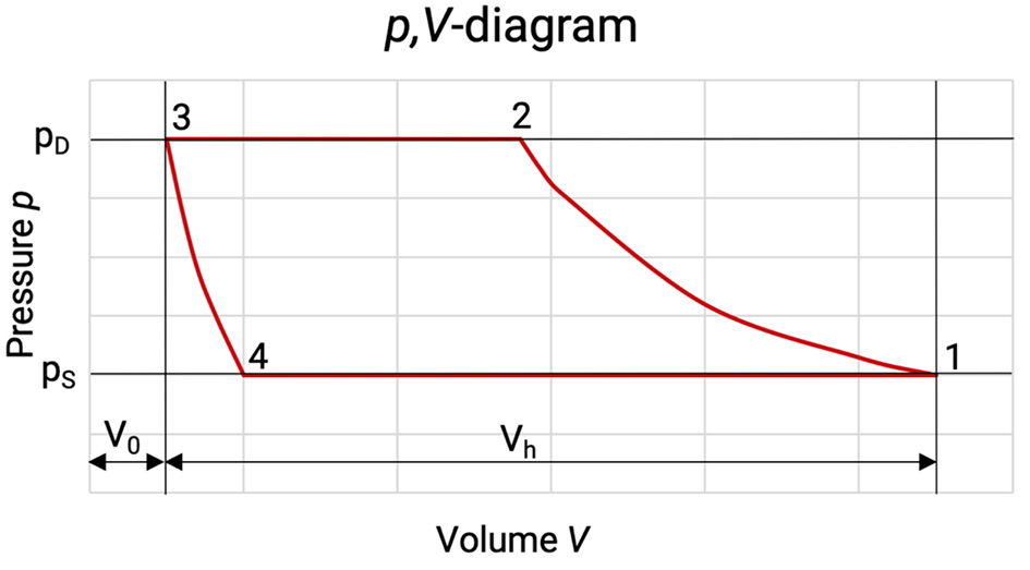
In real compressors, there are irreversible processes in terms of gas velocity, temperature and pressure which only happen in one direction of time and which are unavoidable. These can be superimposed onto the idealised compression cycle. The work as supplied by the piston (internal work) can therefore not be entirely used for the compression of the gas.
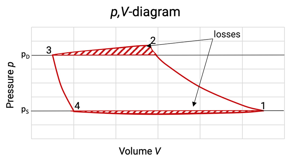
Through these superimposed compensation processes the p,V-diagram changes, see Figure 5.2.
Figure 5.2: p,V-diagram of a compression cycle with losses [0], [33]
The enclosed area of the diagram corresponds to the real internal work per compression cycle. As the mass flow has also changed, the mass specific internal work has to be taken for the evaluation of the losses. The losses due to gas flow in and out the working chamber are highlighted with dashes in the p,V-diagram.
Due to friction losses during the gas flow in and out of the working chamber, the pressure in the cylinder between (4) and (1) is lower than in the suction chamber and higher between (2) and (3) than in the discharge chamber. The pressure loss is at any point proportional to the square of the piston speed. The increase in the area of the p,V-diagram gives the additional work done due to the internal losses.
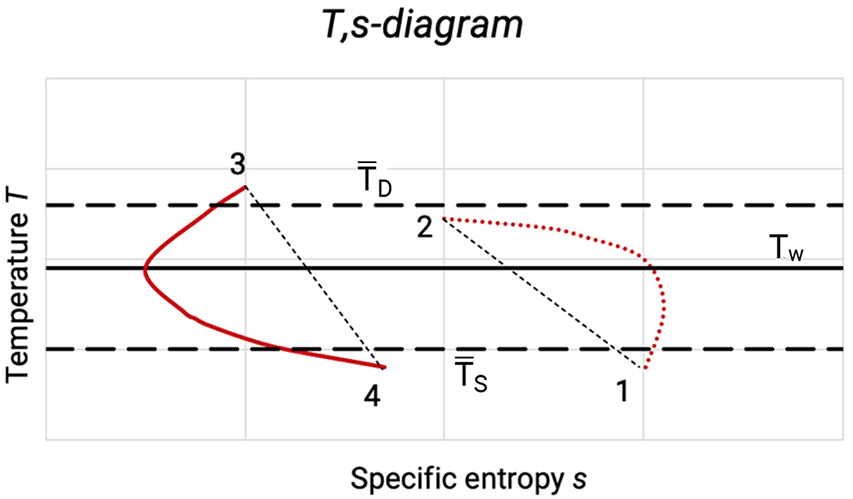
The losses due to heat storage in the cylinder walls can be seen in the T,s-diagram in Figure 5.3. Due to their higher heat capacity, various components of the cylinder have a nearly constant temperature, which lies between the suction and the discharge temperature of the gas.
Figure 5.3: T,s-diagram with losses due to heat exchange of the gas with the working chamber walls [0]
Due to heat transfer on intake of the gas compression starts at T1 > TS. The compression line 1-2 deviates due to the heat transfer (which changes with time) between wall and gas from the polytropic line (dashed) which goes through the start and end point. At the beginning of the compression heat will be transferred to the gas (the specific entropy s increases). When the gas temperature has reached the wall temperature, the direction of heat transfer reverses (specific entropy s decreases).
After the heat transfer of the remaining gas during the pushing out of the gas the re-expansion starts at T3 < T2. The condition of state 3 – 4 deviates for the same reasons from the corresponding polytropic expansion. Due to the heat exchange between the cylinder wall at compression and re-expansion the area of the p,V-diagram and thereby the internal work is increased.
The main losses, however, occur through heating up of the gas during the intake of gas, which reduces the mass flow whilst the internal work remains the same. Whilst bad heat transfer conditions before the cylinder are beneficial, good heat transfer conditions within the cylinder are beneficial as the polytropic exponent is thereby reduced and the ratio between the polytropic and isothermal compression work is reduced.
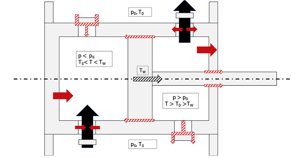
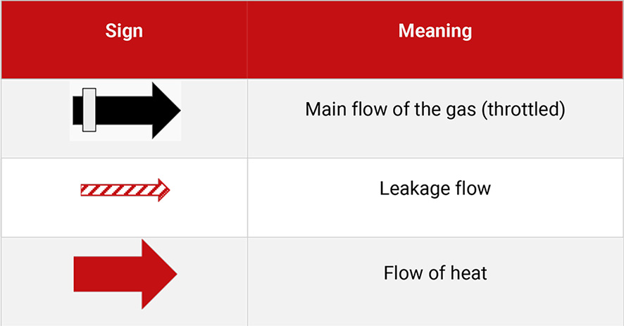
There are also losses due to leakages of the working chamber, because the working chamber is not perfectly sealed against suction and discharge side, even at fully closed valves, see Figure 5.4.
Figure 5.4: Losses due to leakages in the working chamber [0], [33]
Table 5.1 shows the signs of Figure 5.4 with the description.
Table 5.1: Legend to Figure 5.4
There can also occur some leakage through the piston rings and pressure packings either to an adjacent working chamber or to the outside. Leakages of the working chambers do not lead necessarily to an increase of the internal work, but they always cause a reduction in mass flow and thereby to an increase of the specific work (leakage losses).


